Welcome Guest!!!

Thank you for visiting the GM Kappa Performance Forum. This forum is the only performance oriented forum for all GM Kappa Platform Enthusiasts.  We hope you will join and share your experiences.  Becoming a member is FREE! If you want to advertise on this forum, email KappaPerformance at yahoo.com.


Registration required to view the forum attachments. Below is a sample of the current top 25 topics.
Supporting Membership has many advantages.


More information on becoming a supporting member or vendor can be found on the sub forum; Site Help and Suggestions; thread - Supporting Members and Vendors.

Author Topic: How To: Install AVIC D3 Stereo Navigation System  (Read 10854 times)

0 Members and 1 Guest are viewing this topic.

Offline Morfious

  • SMMM 7 Cup Stacking Champion
  • Upgraded Member
  • Master Tech
  • *
  • Posts: 298
  • Karma: +1/-1
  • Location: Morrisville, PA
  • Tryin' to keep the rubber side down since age 2
How To: Install AVIC D3 Stereo Navigation System
« on: January 11, 2009, 08:22:26 AM »
I plan to upgrade this to serve as instructions for anyone interested in installing the Pioneer AVIC D3 into the Solstice.  Here is a overview of what I plan to do for the audio system.  Pics on the right are guides for how I want it to look when finally installed.


I purchased my 2007 GXP with the base stereo and NO onstar since I planned to upgrade from the beginning.  So these parts will work in that application. The only difference I am aware of is using the GMOS-Lan-04 harness if you want to keep the Monsoon amp and onstar. edit (also has input for VSS wire directly on the unit)

Parts List:

Pioneer - AVIC D3 (Head unit)
PAC SWI-PS (Steering Wheel control)
Pioneer - CD-I200 (High Speed iPod Cable)
Pioneer - SIR-PNR2 (Sirius Satellite Radio adapter)
Metra - 95-3302 (Double din dash install kit)
Metra - 40-cr10 (Antenna adapter)
Pioneer - CD-BTB200 (Bluetooth adapter)
METRA - GMOS-LAN-03 (Onstar / chime harness) For NON monsoon system
METRA - GMOS-LAN-04 (Onstar / chime harness) For Monsoon systems (includes VSS wire)
Pioneer - ND-BC2 (Rear view camera)
NAPA - AR201 (12v 30 amp SPDT (Single pole double throw) relay (Needed with older version of GMOS-Lan-03 for blinker "click")

There have been some product modifications and updates since I did my install so a few things may have chantged.  I am recommending everyone use the GMOS-LAN-04 harness now since it includes a VSS wire hookup for the navigation.  It will make it a bit more accurate and you won't need to hook up a relay for the blinker click sound.

The "typical Before Pic"


Most of the bolts were 10mm or 9/32 for the smaller ones.  A few extensions and a swivel head are really needed for some of the more hard to reach areas. This is the look of things after the planning stage and starting to rip everything apart.  The dash pulled apart quite easily with some force.  Just be gentle and work your way around, you will be fine.  Quick note, you do NOT need to remove the shifter as the instructions say to get the IP trim off.  If you turn the shifter ring so it faces vertically you can slide the IP trim over the shifter boot and keep it in place.  My shifter was held in with blue locktite and no allen key I had was going to touch it.


Now on to the really fun part the wiring harness.  I know my way around a soldering iron and have a decent knowledge of schematics and how to read them.  I took all the harnesses into the basement and started connecting it all up.  It went fairly easy, until I started making changes and re-reading that some wires need extra 12 volt accessory connections etc.  What I did in the end (day 2 at 7:30 am) was make a pigtail with 5 ends tapped into the 12v accessory line of the after market harness as well as do the same for the ground.  This turned out to be a great method although it looks a bit messy.  Wire ties and electrical tape were used to try and keep things in good order.  I also tested each component (with the radio in my lap) prior to install just to make sure everything was A-OK.

When making your pigtail tap a few extra lines off the yellow battery line as well.  Sirius, Bluetooth, and the blinker relay should be run from a constant 12v source

ILLUMINATION WIRE - Note the included instructions for the GMOS-LAN-03 adapter are incorrect regarding the illumination wire.  The orange and white (dimmer) wire  from the GMOS adapter should be hooked up to the orange illumination wire in the head unit harness.  This will provide the correct day/night mode navigation operation.  The extra solid orange wire in the GMOS harness may be cut short and capped off.  (In the picture below the incorrect wire is attached.  The orange and white wire on the far left is the correct wire to attach.)


« Last Edit: January 11, 2009, 07:34:03 PM by Morfious »
Mean GXP Delivered 1/30/2007 $MSRP +$2K
Mods:
Pioneer AVIC D3 Nav System
Solo-Performance Street Race exhaust
Debadged
JPM interior (Doors, steering wheel, shifter, console now with 100% more Chuck Norris)
Custom dash and Flush mounted Valentine 1 Radar Detector
O.Z. Ultraleggera wheels with Dunlop DZ101
DDM Works (Big Brake Kit, backbone, intercooler, valve and coil cover)
GXP ZOK Rear sway bar


Offline Morfious

  • SMMM 7 Cup Stacking Champion
  • Upgraded Member
  • Master Tech
  • *
  • Posts: 298
  • Karma: +1/-1
  • Location: Morrisville, PA
  • Tryin' to keep the rubber side down since age 2
Re: Ultimate Avic - D3 Install Thread
« Reply #1 on: January 11, 2009, 08:22:40 AM »
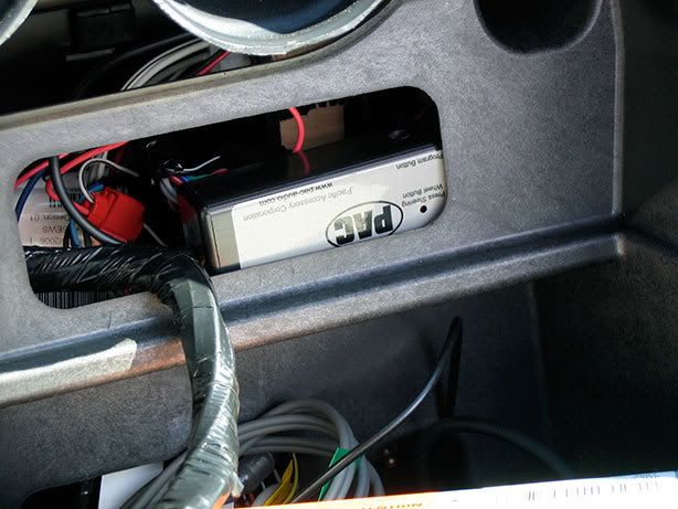
Steering Wheel Adapter SWIPS   This was a fun one to work on.  First of all they have the connectors backwards in the instructions connector 1 is really connector 2 and vice versa.  Everythig else seemed to be in good order though.  The green wire from the SWIPS gets connected to Pin 14 (blue wire) of the vehicle wire harness.  Just take a knife, peel back a bit of the wire covering and use a tap in connector.  The Red wire gets a 12v acc and black to ground as usual.  The other wires may be left alone or trimmed as they are not needed.  Keep the 2 loops of wire in tact though (brown and purple).  With this installed I started to "program" the unit only to find out that it was not working as instructed.  After some choice words and a stiff iced tea I looked over the install sheet again.  It seems I neglected to notice the extra install note for the Solstice that read (attach Pin 11 on C2 (White wire with black stripe) to accessory 12 volt source.  After I calmed myself I tapped into that connector on the vehicle harness and everything worked out as planned.  Here is a shot of where I decided to install the unit.  easy access if I ever need to reprogram it.


Next up was the rear view camera.  The accessory box mounted easily.  Take the 12V and ground (that you made in the earlier wiring harness step) and crimp / solder your connections.  I mounted my box with velcro to try and stop and rattles.


Now in order for the really cool part to work you need to find a circuit that will change when the vehicle is placed in reverse.  This hookup will turn the camera on when you start to backup.  I could not find an easy one, so I just decided to use the passenger side backup light.  Little did I realize that you need to take off the fender well and mud flap in order to get to it.  The wire I tapped into was green and goes to the reverse lights.  The red arrow points to the connection.  The wire was then run down the passenger side of the trunk behind the carpet and down the center waterfall compartment.  It passes under this and hooks up to the radio behind the dash.  (There is a hookup for the reverse light in the passenger footwell area as well Green wire)


As for mounting it, I took off the license plate and stuck the camera to the car with the supplied sticky tape.  I then put the license plate over the tab to help hold the camera in place.  Here is a view from the side to see how small and unobtrusive it is.


I was unable to fully locate the VSS wire and I was getting tired so I opted to leave that out.  Putting everything together was fairly easy and the final results are amazing.


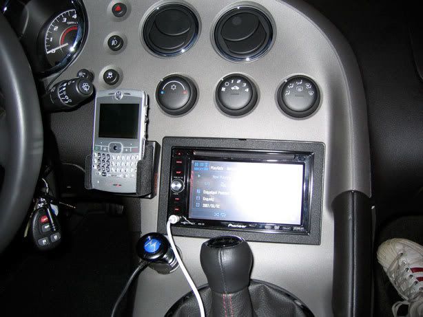
And for my "Hackers" fans,  It looks crispy in the dark too:


iPod cable is plugged into the unit and sits in the glove box for now.  Not sure if I want to put it somewhere else.  When the sirius and Bluetooth adapters are done being backordered I will update my posts with pics and how to info.  The hardest part is going to be finding some more space behind the dash to stuff everything.  It's really jammed back there now.  I have a few scrapes on my hands from wedging them through the small openings feeding the stereo harness back there.


GPS Antennae Placement - The GPS antennae is actually in the center waterfall behind the trim piece.  There is a small shelf on the top of the waterfall storage compartment behind the trim.  It fits perfectly there and is totally out of the way.  Signal reception is perfect.  The white wire you see in the pictures is from my old install, it's a dock connector to 1/8" jack iPod cable.  I was just using it to test the front AV jack.  I'll see if I can get a quick picture of the GPS antenna.  If it's too much I will shoot one when I install the Sirius unit (on Backorder)  I also have some VSS wire info although I did not hook mine up.  Maybe if someone can track this to an easier access point I will give it a try.

Manual Trans 2007 GXP:
VSS High signal Yellow wire to Pin 53 of connector C2 (58 Pins) of ECM
VSS Low  signal  Purple wire to pin 40 of connector C2 (58 Pins) of ECM

Here are some pics of the GPS (and Sirius when it arrives) antenna install Position.  The first pic shows where they are installed.  The other pictures are taken looking down from there.

Trim pulled back showing location of antenna:


Here is the little "shelf" that works out perfectly for the GPS antennae.  I have an almost full signal according to the status bar on the radio.


Well today was more fun and excitement as I ripped apart my Solstice for the second half of the head unit upgrade.  Here is how she looked with her interior ripped out for the second time, ready to start the day:


All that just to install this:


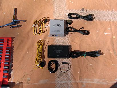
Things went fairly smoothly.  After some test fitting and head scratching I decided to install the sirius unit behind the drivers seat trim panel.  This worked out quite well as the hardest part was fishing the IP bus cable from the head unit to where I have the sirius installed.  Few bloody knuckles, but all went according to plan.  Here is the final resting place for the sirius adapter.  I drilled 2 holes in the rear firewall and used a strip of HD velcro to hold the bottom of the unit firmly in place.  I am confident that my unit will not come loose in adventurous driving conditions.


And here is a clearer shot of where I have the antennas installed.  The reception is better in this location than it is in my Jeep (antennae is on the hood).  Works great and I have had no issues with the unit while driving around today.


This install would have taken less time if I would have waited, but I'm impatient.  Right now everything is working 100% and I am very happy.  There are a few quirks with the Sirius adapter, (memo only works for songs not artists, and only 1 line display of info) but they are minor.  Right now I have the bluetooth adapter tucked into the far right corner of the dash, to the right of the glove box.  I may velcro it to the side if I see it is moving around, but right now it seems stable.  The microphone wire was sNAK3D across the dashboard and up the drivers side windsheild pillar.  I could figure out no great mounting options for the microphone so I taped it into the cutout for the onstar microphone.  It seems to be working just fine and the people I talk to on the phone say they can hear me without problems.  The bluetooth was easy to set up and I was able to transfer several of my contacts at one time over to the unit.  I still have to read the manual to see all of the options and settings, but it's working and that's what's important.

All connections for constant 12v were made at the radio harness, (blinker relay, Sirius, BTB200)  I am quite happy and hope that my instructions and tips here make things easier and more understandable for others.  The Speaker and amp upgrade will come at the end of the summer (as long as no other catastrophes come about first).
« Last Edit: January 11, 2009, 07:29:45 PM by Morfious »
Mean GXP Delivered 1/30/2007 $MSRP +$2K
Mods:
Pioneer AVIC D3 Nav System
Solo-Performance Street Race exhaust
Debadged
JPM interior (Doors, steering wheel, shifter, console now with 100% more Chuck Norris)
Custom dash and Flush mounted Valentine 1 Radar Detector
O.Z. Ultraleggera wheels with Dunlop DZ101
DDM Works (Big Brake Kit, backbone, intercooler, valve and coil cover)
GXP ZOK Rear sway bar


Offline Morfious

  • SMMM 7 Cup Stacking Champion
  • Upgraded Member
  • Master Tech
  • *
  • Posts: 298
  • Karma: +1/-1
  • Location: Morrisville, PA
  • Tryin' to keep the rubber side down since age 2
Re: Ultimate Avic - D3 Install Thread
« Reply #2 on: January 11, 2009, 08:22:59 AM »
The mike routing was a bit difficult.  I ran the wire across the dashboard underneath the gauge cluster.  You will see where to pull up the microphone when you take off the A pillar.  I could not figure a real solid way to mount the mike with screws so I just taped it into position with electrical tape.  There is a ridge in the back of the A pillar where it will fit quite nicely.  I did not have onstar either and this seemed like the best place.  Everyone I have spoken to on the bluetooth adapter says I sound fine (farther away then when using the handset, but no difficulty hearing me at all).
Bypass AVIC D3 information

I take no responsibility for what you do with this information and it may be illegal to do in your state.  I am just passing on information that I have found.

Bypass for this unit is quite easy.  First you have to ground the parking brake wire.  This will make the D3 think that you have your parking brake on at all times.  I used the ground wire in the wiring harness.

Second locate the Yellow wire with a black stripe in the Avic Harness.  It's on the plug with all the red and white stereo plugs.  If you look at the white plastic plug you will notice an empty slot right above this wire.  Using a small screwdriver pry up the plastic plug and pull out the wire.  Replace it into the hole directly above.  Ground this wire as well with the parking brake wire.  Hook everything up and hit reset on the front of the unit.  You are now bypassed.  Here is a picture from the AVIC 411 forums for clarity.


The Base and Redline/GXP have different VSS lines.

2.4l w/ MT: VSS is mounted at the left rear of the transmission.
VSS High Signal is YE wire, terminated on Connector C3, Terminal 66 of the ECM
VSS Low Signal is PU wire, terminated on Connector C3, Terminal 67 of the ECM

C1 is BU with BK case
C2 is BK
C3 is GY with BK case

2.4l w/ AT: OSS is mounted at the right rear of the transmission.
OSS High Signal is YE wire, terminated on Terminal F1 of the TCM
OSS Low Signal is PU wire, terminated on Terminal F2 of the TCM


2.0 with Manual Trans GXP:
VSS High signal Yellow wire to Pin 53 of connector C2 (58 Pins) of ECM
VSS Low signal Purple wire to pin 40 of connector C2 (58 Pins) of ECM


The VSS wire is not mandatory, but it can make navigation a bit more correct, mine is not currently hooked up.  The Swi-PS adapter will allow you to keep the steering wheel controls and is highly recommended it works great!.

Update and a few WIP pictures:

Chris my installer doing his custom thing on the amp rack:


Behold the wonderful devices that make my ears happy the JL Audio ZR series components ($800) and worth every penny of it.


Dynamat installed:


Dynamat on the doors as well (new speakers installed in factory location):


Even more Dynamat (check out the slick crossover mounting position)


I am very happy with the quality and sound of my new system.  I can't wait for the subwoofer to be released so I can complete my system.  The bass response is tremendous even without a sub.
« Last Edit: January 11, 2009, 07:32:46 PM by Morfious »
Mean GXP Delivered 1/30/2007 $MSRP +$2K
Mods:
Pioneer AVIC D3 Nav System
Solo-Performance Street Race exhaust
Debadged
JPM interior (Doors, steering wheel, shifter, console now with 100% more Chuck Norris)
Custom dash and Flush mounted Valentine 1 Radar Detector
O.Z. Ultraleggera wheels with Dunlop DZ101
DDM Works (Big Brake Kit, backbone, intercooler, valve and coil cover)
GXP ZOK Rear sway bar


Offline spicy3480

  • Solo Performance Sales
  • Vendor
  • Gearhead
  • *
  • Posts: 2556
  • Karma: +1/-4
  • Location: New York
Re: How To: Install AVIC D3 Stereo Navigation System
« Reply #3 on: January 11, 2009, 08:01:59 PM »
I can attest to Jason's car...it sounds great and does not have a subwoofer...yet!!  The sound deadening material and the JL components he chose make a huge difference.
Steve Mariano
Solo Performance
516-655-9002 (7 days a week, until midnight EST)
goingsolo2@hotmail.com


2007 Mysterious Solstice GXP
INTRUDER

Offline Gunnys GXP

  • Founding Member
  • Master Tech
  • *
  • Posts: 270
  • Karma: +0/-0
  • Location: Holt, MI
  • SEMPER FI
Re: How To: Install AVIC D3 Stereo Navigation System
« Reply #4 on: February 02, 2009, 03:38:57 PM »
I feel a bit lost.  What is the VSS?
07 Deep GXP auto.  A lot of cosmetic upgrades but not enough performace mods. YET.

Offline Go-N Def

  • Master Detailer
  • Gearhead
  • *
  • Posts: 2142
  • Karma: +0/-1
  • Location: Okinawa, Japan
  • Morally Flexible
Re: How To: Install AVIC D3 Stereo Navigation System
« Reply #5 on: February 02, 2009, 05:33:01 PM »
I can attest to Jason's car...it sounds great and does not have a subwoofer...yet!!  The sound deadening material and the JL components he chose make a huge difference.
I keep telling people that!

Offline DeepBlueGXP

  • KappaPerformance Site Owner
  • Administrator
  • Shop Foreman
  • *
  • Posts: 9226
  • Karma: +13/-6
  • Location: Southern Maryland
  • Displaced Buffalo Bills Fan
    • Kappa Performance Forum
Re: How To: Install AVIC D3 Stereo Navigation System
« Reply #6 on: February 02, 2009, 06:23:15 PM »
VSS is the Variable Speed Sensor wire that allows the radio to increase in volume as you increase speed.

Offline Gunnys GXP

  • Founding Member
  • Master Tech
  • *
  • Posts: 270
  • Karma: +0/-0
  • Location: Holt, MI
  • SEMPER FI
Re: How To: Install AVIC D3 Stereo Navigation System
« Reply #7 on: February 02, 2009, 07:27:57 PM »
VSS is the Variable Speed Sensor wire that allows the radio to increase in volume as you increase speed.

AHH.  Thanks.  Man.  Now that I am at home and can look at the attached pics, I think I am in for a hand full more than just my usual audio install.  I'm a bit nervous now.  You guys need to live closer  :D.
07 Deep GXP auto.  A lot of cosmetic upgrades but not enough performace mods. YET.

Offline Jasontamu

  • Apprentice/Gofer
  • *
  • Posts: 10
  • Karma: +0/-0
Re: How To: Install AVIC D3 Stereo Navigation System
« Reply #8 on: May 06, 2009, 02:55:40 PM »
Great work in cleaning up the write up to a few thread post....

I have done many AVIC-D3 installations.......

Just wanted to help out in saying that the GMOS-LAN-03/04 provides the REVERSE WIRE as well...

so there is no need to hunt for a reverse wire off a tail light or green at the passenger  side footwell........you can make all your connections at the worktable prior to install.

it also provides the parking brake, but who uses that anymore - Bypass rocks!!!

-J

Offline elff

  • Premium Member
  • General Manager
  • *
  • Posts: 11381
  • Karma: +26/-58
  • Location: Keebler Tree House
Re: How To: Install AVIC D3 Stereo Navigation System
« Reply #9 on: May 06, 2009, 08:34:10 PM »
I would like to add that the Kenwood DNX 8120 is another killer option for upgrading the stock radio.

I took a much easier route for my installation.  I handed money to a much more skilled person than myself.
 :lol:
End Result

Kenwood DNX 8120
Integrated Garmin GPS
I have the GM Lan interface
Steering wheel control interface
IPod  cable interface in Glove compartment
HD Radio Upgrade [I'm not a fan of XM or Sirius]
a second USB port in glove compartment
GM Roadster Subwoofer kit consisting of a
      Stock Sub Enclosure with Kicker Competition Sub
      Alpine Amp
I also have a PS2/3 Cable hardwired to the AV1 port


I love it.

Offline Jasontamu

  • Apprentice/Gofer
  • *
  • Posts: 10
  • Karma: +0/-0
Re: How To: Install AVIC D3 Stereo Navigation System
« Reply #10 on: May 07, 2009, 08:20:44 AM »
^^ hey not bad...that looks good...

Offline Jasontamu

  • Apprentice/Gofer
  • *
  • Posts: 10
  • Karma: +0/-0
Re: How To: Install AVIC D3 Stereo Navigation System
« Reply #11 on: May 07, 2009, 09:05:32 AM »
Oh, another thing i would like to mention is that if you decide to use a METRA product, either GMOS-LAN-03/04 you have to run to your local autoparts store and purchase a "loud" flasher relay to make the noise. Most auto parts stores know what your talking about when you ask them, but its a typical item. its will say on the package "LOUD"...

if you know relays, all your doing is hooking up two wires to the "coil" to make the "gate" slap open and close and if you choose a relay with the loud feature, it pretty much is a gate that makes noise when it physically opens and closes hitting back and forth.

The GMOS-LAN-XX instructions tells you how to hook up the wiring to do it.

or instead of dealing with your local auto parts store you can purchase the METRA loud relay - METRA E-123 when ordering your parts for install.

Review the wiring here:


as you can see from the wiring, there are two wires (black/white) next to the black yellow on the lower right hand side of the attached picture.

It already has butt splices on them, set up to accept the blinker noise making relay of your choice. you hook up the (black/white) and a constant power to the relay noise/click maker and rock and roll...

-J


Offline Jasontamu

  • Apprentice/Gofer
  • *
  • Posts: 10
  • Karma: +0/-0
Re: How To: Install AVIC D3 Stereo Navigation System
« Reply #12 on: May 07, 2009, 09:10:18 AM »
HOWEVER.......

i know this may seem like a curve ball, but............

if you wanna have the least worry free installation, especially with the SWI-PS steering control adapter, then i recommend installing with the PAC-AUDIO HARNESS (OS-311) instead of the METRA GMOS-LAN-XX harness.....

Reason being:
1. Pac harness already has the wires connected for the SWI-PS on their kit -
(see in the attachment below the reference for the green wire for the SWI-X where it mentions SWC output wire - program version 1).

2. Blinker click relay is integrated - (SEE THE CM-X CHIME MODULE in attachment below)....so the unit itself does this, no need to wire up a blinker clicking relay from local auto parts store, or purchase a metra E-123.

See PAC OS-311 here:
http://img228.imageshack.us/my.php?image=pacaudioos311.pdf

-J


Powered by EzPortal